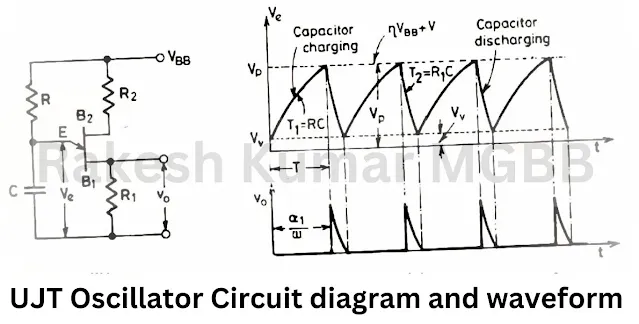
- The UJT (Uni Junction Transistor) is a semiconductor device that has only one junction, and it is widely used in relaxation oscillators. The UJT relaxation oscillator utilizes the characteristics of the UJT, including its negative resistance region, to generate a timing interval.
- The unijunction transistor (UJT) can function as a highly efficient switch and a relaxation oscillator.
- The external resistances R1, R2 are small in comparison with the internal resistances RB1,RB2 of UJT bases.
- The charging resistance R should be such that its load line intersects the device characteristics only in the negative resistance region.
- In the oscillator mode, when a source voltage VBB is applied, the capacitor C charges through a resistor R towards VBB.
- During this charging, emitter circuit of UJT is an open circuit. the capacitor voltage Vc equal to emitter voltage Ve is given by Vc = Ve = VBB(1-e-t/RC).
- The time constant of the charge circuit is τ1 = RC.
- When the emitter voltage Ve (or Vc) reaches the peak-point voltage Vp (= ηVBB +VD),the UJT turns on, and the capacitor C rapidly discharges through a low resistance R1 with a time constant τ2 = R1C.
- Here τ2 is much smaller than τ1.
- When the emitter voltage decays to the valley-point voltage Vv,UJT turns off.
- The time T required for the capacitor C to charge from the initial voltage Vv to the peak-point voltage Vp through the resistance R can be obtained using the equation T = 1/f = RC In [1/(1 - η)].
- The firing angle α1, which represents the time delay before the UJT turns on, can be calculated as α1 = ωT = ωRC In [1/(1-η)].where ω is the angular frequency of UJT oscillator.
- The amplitude of the pulse voltage is obtained by drawing a load line Bb for R on the UJT characteristic curve.
- The value of R1 should be sufficiently small to ensure that the leakage current drop across R1 when the UJT is off does not trigger the SCR.
- The value of R2 can be calculated from the relation R2 = 104 / (ηVBB) to compensate for the thermal effects on the UJT's forward characteristics.
- The width of the triggering pulse can be taken as R1C.
- The circuit cannot function as an oscillator if the load line for R intersects the UJT characteristics in the region CQ.
- The maximum and minimum values of the charging resistor R and the oscillator output frequency are determined by the peak-point and valley-point values of the UJT's voltage and current.
- The maximum value of R is given by RMax = [VBB - (ηVBB + VD)] / Ip.
- The minimum value of R is given by RMin = (VBB - Vv) / Iv.
- These characteristics and modes of operation make the UJT an excellent switch for applications requiring fast switching times, typically in the nanosecond range. The UJT relaxation oscillator takes advantage of these properties to create a timing interval using a charging capacitor and the rapid discharge of the same capacitor.
 |
| Unijunction transistor oscillator circuit diagram and waveform |
Applications of relaxation oscillator
Relaxation oscillators are used in function generators, electronic beepers, SMPS (Switched-Mode Power Supplies), inverters, blinkers, and voltage controlled oscillators.
Comments