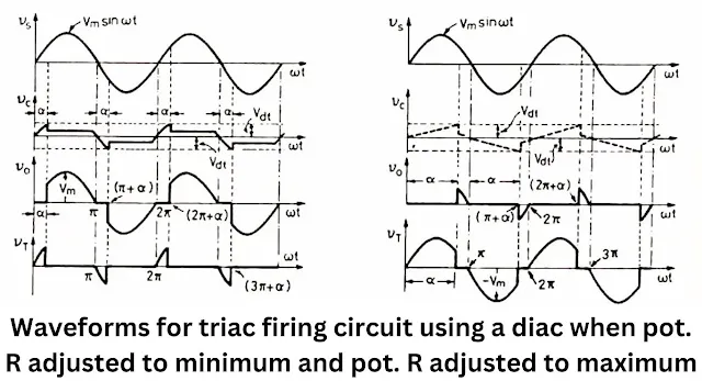
- A triac firing circuit is used to control the power delivered to a load by adjusting the firing angle of a triac. The circuit utilizes a diac for triggering the triac at the desired phase angle.
- Resistor R is a variable resistor that controls the charging time of capacitor C and, consequently, the firing angle of the triac. When R is set to a lower value, the charging time is reduced, resulting in a smaller firing angle. Conversely, when R is set to a higher value, the firing angle increases.
- Resistor R1 has a constant resistance and serves to protect the diac and the gate of the triac from being exposed to the full supply voltage.
- Resistor R2 limits the current flowing through the diac and the triac gate when the diac turns on.
- Capacitor C charges up to the breakdown voltage of the diac, at which point the diac turns on. This causes the capacitor to discharge rapidly, creating a pulse that is applied across the triac gate, turning it on.
- Once the triac is turned on at a specific firing angle (alpha₁), the source voltage (v_s) appears across the load during the positive half cycle for (π - alpha) radians.
- When the source voltage (v_s) becomes zero at omega*t = π (where omega is the angular frequency and t is time), the triac turns off.
- After omega*t = π/2, the capacitor C charges again, but with the lower plate being positive. When the capacitor voltage (v_c) reaches the breakdown voltage of the diac, both the diac and the triac turn on again, and v_0 appears across the load during the negative half cycle for (π - alpha) radians.
- The above process repeats, and the triac turns off again at cot = 2n, where n is an integer.
- The waveforms shown in Figure represent the idealized behavior of the circuit components. However, in practice, the waveforms for the positive and negative half cycles of the load voltage may not be symmetrical due to hysteresis present in the capacitor. This hysteresis causes the capacitor to retain some charge even when the source voltage falls to zero. To achieve symmetrical waveforms, additional components such as resistor R3 and capacitor C1 can be employed.
- This circuit is commercially used for controlling the power in lamp dimmers, heat convertors, speed control of fans etc.When controlling inductive loads, a snubber circuit is typically employed across the triac to protect it from voltage spikes and transients.
FAQ
Q1:What is meant by triac firing circuit?
A triac firing circuit refers to a circuit that controls the firing or triggering of a triac, which is a type of electronic device used for power control in AC circuits. The firing circuit is responsible for initiating the conduction of the triac, allowing the flow of current through the device. By controlling the firing angle, the triac can regulate the amount of power delivered to a load.
Q2:Why DIAC is used to trigger TRIAC?
DIAC (Diode for Alternating Current) is used to trigger TRIAC (Triode for Alternating Current) because the DIAC is a bidirectional device that can conduct current in both directions when a certain voltage threshold is reached. When connected in series with the gate terminal of the TRIAC, the DIAC helps to provide a controlled triggering mechanism for the TRIAC by supplying a pulse of current to the gate terminal when the voltage across it reaches the DIAC's threshold. This allows the TRIAC to turn on and conduct current through the main terminals.


Comments